|


 |  |

| Afaceri | Agricultura | Comunicare | Constructii | Contabilitate | Contracte |
| Economie | Finante | Management | Marketing | Transporturi |
Electrica
|
|
Qdidactic » bani & cariera » constructii » electrica Amplificator de 20wati / 4 ohmi - schema electrica |
Amplificator de 20wati / 4 ohmi - schema electrica
Amplificator de 20wati / 4 ohmi
SCHEMATIC

2N3055 - absolute base
model
2N3055 (the output transistors) must be on a substantial (rather BIG) heatsink -
The design of heatsinks by Rod Elliot
BD 139 also need heatsinks. These do not need to be large.

BC559 - without heatsinks

About HEATSINKS
POWER SUPPLY

(AC filter is not necessarily)

I recommend Capacitance Multiplier Power Supply For Class-A Amplifiers.
Amp sounds better.
Capacitance Multiplier - Design Considerations (by Rod Elliott)
The only real thing to worry about is the degree of filtering needed! We must
assume that at least 3 Volts will be lost across the capacitance-multiplier
filter, to ensure that the DC input (including ripple component) always exceeds
the output voltage.
Because there is no regulation, the power amplifier must be capable of accepting
the voltage variations from the mains - every standard power amplifier in existence
does this quite happily now, so it is obviously not a problem. Note that the
output power is affected, but this happens with all amps, and cannot be avoided
without a regulator.
Figure 2 shows the basic configuration
of a capacitance-multiplier filter, where the capacitance appearing at the base
of the output device is effectively multiplied by the gain of the device - thus
a 1000uF capacitor appears (electrically) to be a 1 Farad (yes, 1,000,000uF)
cap, assuming a gain of 1000 in the output device.
One could simply use a pair of 1F caps for a dual supply, but I have noticed
a dearth of such devices (other than the 5V 'Supercaps' used for memory backup
in computers). Since they will need to be rated at about 35V, and be capable
of considerable ripple current, I cannot help but feel that this is not a viable
option.
Both methods will provide a ripple of well under less than 5mV RMS, but the
multiplier has the advantage of removing the triangular waveform - it is not
a sinewave, but has a much lower harmonic content than would be the case with
a 1F capacitor.
-------- ----- ------ -------- ----- ------ ----- ----- ----
Simple Power supply: (acceptable)

If you want to decrease dissipation - use two output transistors in parallel:

My comment: Sound is wonderfull.
SCHEMATIC
2N3055 - absolute base
model
 (Not
recommended plastic case transistors)
(Not
recommended plastic case transistors)
2N3055 (the output transistors) must be on a substantial (rather BIG) heatsink -The design of heatsinks by Rod Elliot
BD 139 also need heatsinks. These do not need to be large.
BC559 - without heatsinks
About HEATSINKS
Important
!!
Before applying power, set P1 to the middle of its travel, and P2 to maximum
resistance (minimum current).
Be very careful - if you accidentally set P2 to minimum resistance the amp will probably self destruct itself - more or less immediately.
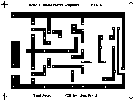
PCB:


PCB - Mirror
Measured Performance:
|
Supply Voltage |
40V |
|
Quiescent Current |
1.7A |
|
Maximum power 8 Ohms |
20W (15W) |
|
Output Noise (unweighted) |
<1 mV |
|
Distortion @ 1kHz, 15W |
< 0.2% |
|
Output Impedance |
0.378 Ohm |
|
Frequency Response (-0.5dB @ 1W) |
<10Hz to>50kHz |
Other acceptable Supply Voltage & Current combinations:
|
Z (ohms) |
Volts |
Iq (Amps) |
Diss. (W) |
Power |
|
|
|
|
|
|
|
|
|
|
|
|
|
|
|
|
|
|
|
|
|
|
|
|
POWER SUPPLY
(AC filter is not necessarily)
I recommend Capacitance Multiplier Power Supply For Class-A Amplifiers.
Amp sounds better.
Capacitance Multiplier - Design Considerations (by Rod Elliott)
The only real thing to worry about is the degree of filtering needed! We must
assume that at least 3 Volts will be lost across the capacitance-multiplier
filter, to ensure that the DC input (including ripple component) always exceeds
the output voltage.
Because there is no regulation, the power amplifier must be capable of accepting
the voltage variations from the mains - every standard power amplifier in existence
does this quite happily now, so it is obviously not a problem. Note that the
output power is affected, but this happens with all amps, and cannot be avoided
without a regulator.
Figure 2 shows the basic configuration
of a capacitance-multiplier filter, where the capacitance appearing at the base
of the output device is effectively multiplied by the gain of the device - thus
a 1000uF capacitor appears (electrically) to be a 1 Farad (yes, 1,000,000uF)
cap, assuming a gain of 1000 in the output device.
One could simply use a pair of 1F caps for a dual supply, but I have noticed
a dearth of such devices (other than the 5V 'Supercaps' used for memory backup
in computers). Since they will need to be rated at about 35V, and be capable
of considerable ripple current, I cannot help but feel that this is not a viable
option.
Both methods will provide a ripple of well under less than 5mV RMS, but the
multiplier has the advantage of removing the triangular waveform - it is not
a sinewave, but has a much lower harmonic content than would be the case with
a 1F capacitor.
-------- ----- ------ -------- ----- ------ ----- ----- ----
Simple Power supply: (acceptable)
If you want to decrease dissipation - use two output transistors in parallel:
My comment: Sound is wonderfull.
| Contact |- ia legatura cu noi -| | |
| Adauga document |- pune-ti documente online -| | |
| Termeni & conditii de utilizare |- politica de cookies si de confidentialitate -| | |
| Copyright © |- 2026 - Toate drepturile rezervate -| |
|
|
|||||||
|
|||||||
|
|||||||
Referate pe aceeasi tema | |||||||
|
| |||||||
|
|||||||
|
|
|||||||